Abigail's Controller System Overview & Diagnosis Version 1
First released in 2015. This system came in 2 different controller housing designs and was comprised of 2 or more Doppler sensors, a main controller and drivers display. . Click to view more. Verify the part images match your system before performing any diagnosis. You can contact us to help verify the system you have.
V1 2015-2016
Verify you have V1 2015 Abigail's system
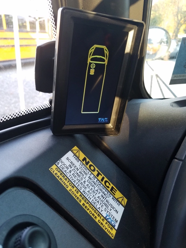
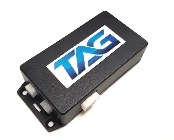
First released in 2015. This system came in 2 different controller housing designs and was comprised of 2 or more Doppler sensors, a main controller and drivers display. Verify the part images match your system before performing any diagnosis. You can contact us to help verify the system you have. Your controller unit may look like the images here.
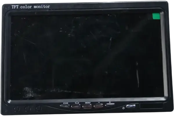
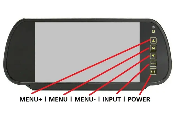
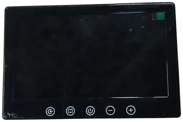
The Display may look like the image here. You can contact us to help verify the system you have.
V1 Concerns and Solutions
Display shows "ERROR" "CAN ERROR" or similar
- System is looking for a Doppler sensor but can not find one or more.
- Check all connections at front and rear mounted sensors and connections at controller. Check there are no cut or torn sensor cables.
- If problem persists contact Tech Support.
Display shows blue screen
- System is looking at the wrong input channel.
- Press the input button on the back of the display.
- If problem persists contact Tech Support.
Display does not turn on
- System may not have power or ground connection
- Locate the controller box, you can trace the display cable to find its mounting location. Verify there is a red or blue glow coming from inside the box (this validates the system us powered up).
- If not powered up check the fuse, the ground connection and the power connection to the vehicle
- Locate the controller box, you can trace the display cable to find its mounting location. Verify there is a red or blue glow coming from inside the box (this validates the system us powered up).
- Verify the white 4 pin connection for the display is secure in the controller box. the plug for the display is seen in.
- If problem persists contact Tech Support.
V3.0 - 3.6 Remote Programming Instructions
WARNING
DO NOT adjust settings unless you are familiar with them. Some settings cannot be undone and may require reprogramming by a technician or sending the unit back for service.
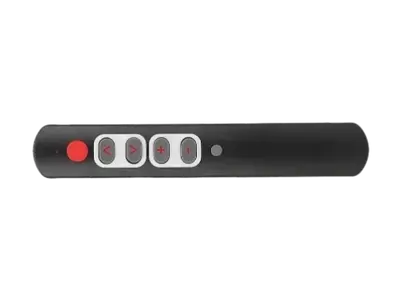
V3.X remote control
This remote is compatible with all 3.X systems, including versions 3.0, 3.5, and 3.6.
Programming instructions
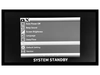
Version 3.5 – 3.6 must be in “STANDBY” mode to enter any of the menu options. This is recommended but not required on V3.0.
Formatting Micro SD V3.0
- Press the “+” plus button two times.
- Press the “^” up arow button three times.
- Press the “O” round red button two times.
Formatting Micro SD V3.0
- Press the “+” plus button two times.
- Press the “^” up arow button three times.
- Press the “O” round red button two times.
Other programming
When modifying some of the menu functions the remote buttons will function differently then laid out above.
Abigail's Controller System Overview & Diagnosis Version 2
Replacing V1 in 2016. This system came in 2 different display sizes and was comprised of 2 ultra wide view cameras, optional Doppler sensors, a main controller and drivers display. . Click to view more. Verify the part images match your system before performing any diagnosis. You can contact us to help verify the system you have.
V2 2016-2020
Verify you have V2 2016 - 2020 Abigail's System
Replacing V1 in 2016. This system came in 2 different display sizes. The system was comprised of 2 ultra wide view cameras, optional Doppler sensors, a main controller and drivers display.
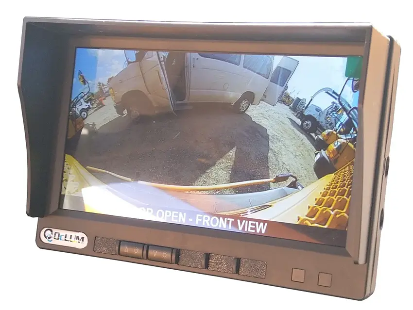
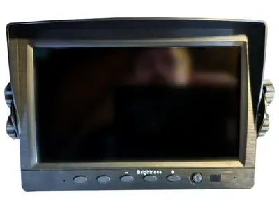
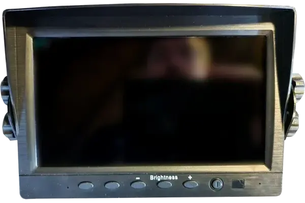
Verify the part images match your system before performing any diagnosis. You can contact us to help verify the system you have. . This revision has a separate controller and drivers display. The Display unit should look like the images here.
Your display may have silver buttons or flat buttons like this image. There were a few other lesser used displays. You can see those in Additional images shown below
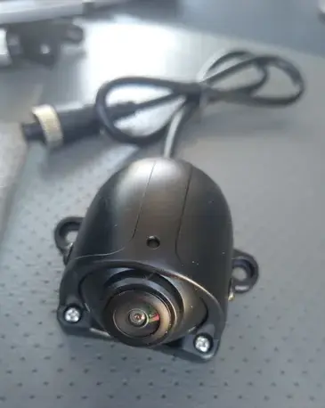
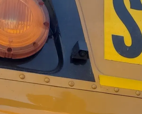
cameras used on the V2 can be identified by the stainless steel (sometimes painted black) Sheetmetal housing with the camera sticking out of the bottom.. The harnesses for the camera are small push type. Here is a camera mounted on rear of a full sized school bus.
The V2 system controller was produced in a few variations. It will look similar to this image. You can trace the display cable back to the controller to locate its mounting location.
V3+ Concerns and Solutions
Display does not turn on
- Press the power button on the display, it may be shut off.
- System may not have power or ground connection
- Locate the controller box.
- Follow the cable coming from the back of the display to locate the controller.
- .Verify there is a red or blue glow coming from the box (this validates the system us powered up).
- If not powered up check the fuse, the ground connection and the power connection to the vehicle
- Locate the controller box.
- Verify the white 4 pin connection for the display is secure in the controller box. the plug for the display.
- An image of the connection points can be found below.
- There is a connection in the display harness about 10 inches from the display. Make sure this round connector is seated properly.
- If problem persists contact Tech Support.
Display shows "NO SIGNAL" "NO INPUT" or similar.
- The display is looking at the wrong input channel.
- Press the input button on the display. View different versions of the display in the images below
- If problem persists contact Tech Support.
Display shows blue screen
- The display is looking at the wrong input channel.
- Press the input button on the display. View different versions of the display in the images below
- If problem persists contact Tech Support.
Front camera does not display when door open
- Does the text “FRONT DOOR OPEN” display on the screen?
- If Yes.
- Locate the controller and swap the camera connections for the front and rear camera. This will eliminate an issue with the controller and determine if the camera and or harness could be a concern.
- Follow the cable coming from the back of the display to the controller
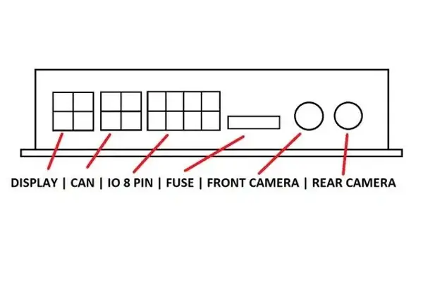
- An image of the controller connections will be shown below.
- Contact Tech Support for replacement parts
- If NO
- If Yes.
- If the vehicle is a caravan, ford transit, Pacifica or other passenger car based platform; the dome light must be in the normal operating position. The dome light triggers the door signal so it must turn on with doors open and shut off when doors closed.
- Locate the controller and trace the purple, pink or green wire coming from the 8 pin connector on the controller. Depending on the vehicle this will be the trigger wire to activate the door signal. Verify this wire is not loose or disconnected.
- Contact Tech Support for replacement parts
Rear camera does not display when in reverse
Does the text “REVERSE ACTIVE” display on the screen?
- If YES.
- Locate the controller and swap the camera connections for the front and rear camera. This will eliminate an issue with the controller and determine if the camera and or harness could be a concern.
- Follow the cable coming from the back of the display to the controller
- An image of the controller connections will be shown below.
- Contact Tech Support for replacement parts
- If NO
- Locate the controller and trace the blue wire coming from the 8 pin connector on the controller. This will be the trigger wire to activate the reverse signal. Verify this wire is not loose or disconnected, wire may run outside and under the vehicle.
- Contact Tech Support for replacement parts
Rear camera does not display when in reverse
- Contact Tech Support for instructions on this update.
Here is an image of the most common V2 system controller . Not all versions have the CAN connector installed
Wiring V3+
- BLUE
- Reverse trigger (can NOT activate via back door opening, only reverse signal)
- 12v +
- Reverse trigger (can NOT activate via back door opening, only reverse signal)
- GREEN
- Door Trigger
- 12v + (only one door trigger is needed)
- Door Trigger
- PURPLE (Pink)
- Door Trigger
- 12v – (only one door trigger is needed)
- Door Trigger
- RED
- Power
- 12v + Ignition signal (on with engine on)
- Power
- BLACK
- Ground
- 12v –
- Ground
Additional Images of the V2 System for Information and Identification
Abigail's Controller System Overview & Diagnosis Version 3.0 - 3.5
Replacing V2 in October 2019. This system came with optional recording and was comprised of 2 ultra wide cameras, up 4 total. Optional Sonar or Doppler sensors were available. This revision has an intergraded controller and drivers display. Click to view more. Verify the part images match your system before performing any diagnosis. You can contact us to help verify the system you have.
V3.0 2021-2024
Verify you have V3.0 or V3.5, 2021 Abigail's System
The V3.6 system launched September 2024, adding to our current offerings. Based on customer input, this revision adds a quick connect to the display harnessing for easy replacement sand repairs. This system came with optional recording and was comprised of 2 ultra wide cameras, up 4 total. Optional Sonar or Doppler sensors were available. This revision has an intergraded controller and drivers display. The controller/Display unit should look like the images here.
The 3.0 system launched October 2019, replacing the V2 system. This system came with optional recording and was comprised of 2 ultra wide cameras, up 4 total. Optional Sonar or Doppler sensors were available. This revision has an intergraded controller and drivers display. The controller/Display unit should look like the images here.
You will see the display has mounting screws on the side and a large metal base. There is an option to mount the display from the back, but you will see the threaded holes on the side.
The cameras used on the V3+ can be identified by the black cast aluminum housing and the 2 screw tabs. The harnesses for the camera are a threaded type with rubber boots to protect from weather. Here is a camera mounted on the front of a Thomas C2
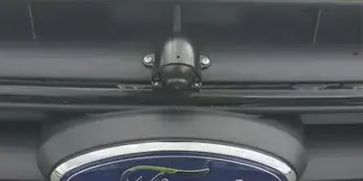
Here mounted on the front of a Ford Transit
Here you can see an up-close image of the V3.0 camera.
The harness has no marking on it.
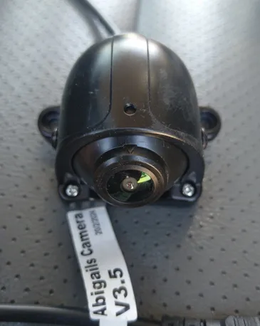
Here you can see an up-close image of the V3.5 camera.
The harness on this sample has the 3.5 marking tag.
V3+ Concerns and Solutions
Display does not turn on
- If the system is a V3.0 there may be a software update needed. You can attempt to reset the system as outlined here.
- If this fixes your concern you should contact Tech Support for the most up to date firmware.
- System may not have power or ground connection
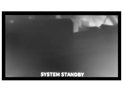
- When ignition is on the display should either show the active camera or a standby screen.
- If not powered up check the fuse, the ground connection and the power connection to the vehicle
- Track the cable coming from the back of the display and locate the connection points for the signal wires.
- If not powered up check the fuse, the ground connection and the power connection to the vehicle
- When ignition is on the display should either show the active camera or a standby screen.
- Using the wiring schematic shown below, verify all connections are made.
- Verify all signals are receiving the correct ground or power.
- Try performing a factory reset. (process outlined below)
- If problem persists contact Tech Support.
Display does not shut off
- If the system is a V3.0 there may be a software update needed. You can attempt to reset the system as outlined here.
- If this fixes your concern you should contact Tech Support for the most up to date firmware.
- Try performing a system reset. (outlined below) here.
- After the quick reset was performed, if you are having issues still you can power cycle the unit.
- disconnect the power, ground and accessory wires for the controller. Leave the system disconnected for 60 seconds then reconnect.
- After the quick reset was performed, if you are having issues still you can power cycle the unit.
- You may have a failed or faulty Micro SD card.
- Some units are equipped with recording functionality. If the Micro SD card has failed it may lock the system as it tries to read and write to a faulty card.
- Remove the card and attempt a system reset.
- If this fixes your concern you should contact Tech Support for a replacement Micro SD card.
- If you are still having issues, please contact Tech Support.
- Some units are equipped with recording functionality. If the Micro SD card has failed it may lock the system as it tries to read and write to a faulty card.
Display indicates the Micro SD card is missing or needs to be formatted.
- You may have a failed dirty or dislodged Micro SD card.
- Some units are equipped with recording functionality. If the Micro SD card has an issue it may show an error on startup or as the system changes viewing states.
- Verify you have a card inserted and its not missing.
- Remove the card and clean the contacts with isopropyl alcohol or electronics cleaner
- You can attempt to reformat the card with the programming remote (outlined below).
- If the issue persists you will need to contact Tech Support for a replacement Micro SD card.
- Some units are equipped with recording functionality. If the Micro SD card has an issue it may show an error on startup or as the system changes viewing states.
Screen shows distorted green/grey squiggly image when showing camera view.
- The controller you are using is programmed for the wrong camera type. V3.0 controllers will only function with V3.0 cameras. However the V3.5 can be programmed to function with both the V3.0 and V3.5 style cameras.
- If you have just replaced a camera or controller you will need to contact tech support or install the correct camera type.
- If problem persists contact Tech Support.
Front camera does not display when door open
- Does the text “DOOR OPEN – FRONT VIEW” display on the screen?
- If YES.
- Track the cable coming from the back of the display and locate the connection points for the cameras. These are round threaded connectors.
- Swap the camera connections for the front and rear camera. This will eliminate an issue with the controller and determine if the camera and or harness could be a concern.
- Contact Tech Support for replacement parts
- Track the cable coming from the back of the display and locate the connection points for the cameras. These are round threaded connectors.
- If NO
- If the vehicle is a caravan, transit, Pacifica or other passenger car based platform; the dome light must be in the normal operating position. The dome light triggers the door signal so it must turn on with doors open and shut off when doors closed.
- Track the wire coming from the back of the display and locate the connection points for the signal wires.
- Using the wiring schematic listed below, verify all connections are made properly. Depending on the vehicle, the trigger wire to activate the door signal color may be different.
- Try performing a system reset. (outlined below) here.
- Contact Tech Support for replacement parts
- If YES.
Rear camera does not display when in reverse
- Does the text “REVERSE ACTIVE – REAR VIEW” display on the screen?
- If YES.
- Track the cable coming from the back of the display and locate the connection points for the cameras. These are round threaded connectors.
- Swap the camera connections for the front and rear camera. This will eliminate an issue with the controller and determine if the camera and or harness could be a concern.
- Contact Tech Support for replacement parts
- Track the cable coming from the back of the display and locate the connection points for the cameras. These are round threaded connectors.
- If NO
- Track the cable coming from the back of the display and locate the connection points for the signal wires.
- Using the wiring schematic shown below, verify all connections are made properly.
- Try performing a system reset. (outlined below) here.
- Contact Tech Support for replacement parts
- Track the cable coming from the back of the display and locate the connection points for the signal wires.
- If YES.
Rear camera turns on when opening the back door of the vehicle
- Contact Tech Support for instructions on this update.
Display turns on during reverse activation and shuts off. Some times turns on when front door open in
- The power and accessory wires may have been swapped on the vehicle inadvertently.
- Using the wiring schematic shown below, verify all connections are made properly.
- If problem persists contact Tech Support.
- Try performing a system reset. (outlined below) here.
- After the quick reset was performed, if you are having issues still you can power cycle the unit.
- disconnect the power, ground and accessory wires for the controller. Leave the system disconnected for 60 seconds then reconnect.
- If you are still having issues, please contact Tech Support.
- After the quick reset was performed, if you are having issues still you can power cycle the unit.
Perform System Reset V3.0 - V3.5
Delete Group
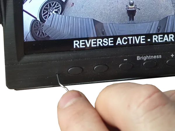
- A quick system reset can be performed by inserting a paperclip into the small hole on the front of the display on the lower left as shown in the image.
- Pressing a paperclip in the small hole, you will feel a detent button and hear a small click. Keep the button inside the small hole pressed for a minimum of 10 seconds. After releasing, you will see the system reboot.
- Caution not to insert into the hole on the right hand side. This is the display microphone, If your system has recording activated.
- After the quick reset was performed, if you are having issues still you can power cycle the unit.
- disconnect the power, ground and accessory wires for the controller. Leave the system disconnected for 60 seconds then reconnect
- If you are still having issues, please contact Tech Support.
It is very uncommon to perform a system reset on a V3.5 but if needed the reset button can be found on the back of the monitor just adjacent to the Micro SD card slot.
Wiring V3+
- BLUE
- Reverse trigger (must NOT activate via back door opening, only reverse signal)
12v + signal from vehicle reverse activation
- Reverse trigger (must NOT activate via back door opening, only reverse signal)
- GREEN
- Door Trigger
- 12v + (only one door trigger is needed). Power signal from vehicle.
- Door Trigger
- PURPLE
- Door Trigger
- 12v – (only one door trigger is needed). Ground signal from vehicle.
- Door Trigger
- RED
- Ignition
- 12v + Ignition signal (on with engine on). Off when vehicle off.
- Ignition
- YELLOW
- Power
- 12v + Battery constant
- Power
- BLACK
- Ground
- 12v –
- Ground
- GREY
- Alarm input from Occupant detection sensors or other
- 12v +
- Alarm input from Occupant detection sensors or other
- CAMERAS
- (Front-Rear) for Abigail’s System
- (AUX1-AUX2) extra inputs for internal DVR recording.
Additional Images of the V3+ system for information and identification
Abigail's Controller System Overview & Diagnosis Version 3.0 - 3.5
Replacing V3.0 in January 2024. This system came with optional recording and was comprised of 2 ultra wide cameras, up 4 total. Optional Sonar or Doppler sensors were available. This revision has an intergraded controller and drivers display. Click to view more. Verify the part images match your system before performing any diagnosis. You can contact us to help verify the system you have.
V3.5 2024-Current
Verify you have V3.0 or V3.5, 2021 Abigail's System
The V3.6 system launched September 2024, adding to our current offerings. Based on customer input, this revision adds a quick connect to the display harnessing for easy replacement sand repairs. This system came with optional recording and was comprised of 2 ultra wide cameras, up 4 total. Optional Sonar or Doppler sensors were available. This revision has an intergraded controller and drivers display. The controller/Display unit should look like the images here.
The 3.0 system launched October 2019, replacing the V2 system. This system came with optional recording and was comprised of 2 ultra wide cameras, up 4 total. Optional Sonar or Doppler sensors were available. This revision has an intergraded controller and drivers display. The controller/Display unit should look like the images here.
You will see the display has mounting screws on the side and a large metal base. There is an option to mount the display from the back, but you will see the threaded holes on the side.
The cameras used on the V3+ can be identified by the black cast aluminum housing and the 2 screw tabs. The harnesses for the camera are a threaded type with rubber boots to protect from weather. Here is a camera mounted on the front of a Thomas C2
Here mounted on the front of a Ford Transit
Here you can see an up-close image of the V3.0 camera.
The harness has no marking on it.
Here you can see an up-close image of the V3.5 camera.
The harness on this sample has the 3.5 marking tag.
V3+ Concerns and Solutions
Display does not turn on
- If the system is a V3.0 there may be a software update needed. You can attempt to reset the system as outlined here.
- If this fixes your concern you should contact Tech Support for the most up to date firmware.
- System may not have power or ground connection
- When ignition is on the display should either show the active camera or a standby screen.
- If not powered up check the fuse, the ground connection and the power connection to the vehicle
- Track the cable coming from the back of the display and locate the connection points for the signal wires.
- If not powered up check the fuse, the ground connection and the power connection to the vehicle
- When ignition is on the display should either show the active camera or a standby screen.
- Using the wiring schematic shown below, verify all connections are made.
- Verify all signals are receiving the correct ground or power.
- Try performing a factory reset. (process outlined below)
- If problem persists contact Tech Support.
Display does not shut off
- If the system is a V3.0 there may be a software update needed. You can attempt to reset the system as outlined here.
- If this fixes your concern you should contact Tech Support for the most up to date firmware.
- Try performing a system reset. (outlined below) here.
- After the quick reset was performed, if you are having issues still you can power cycle the unit.
- disconnect the power, ground and accessory wires for the controller. Leave the system disconnected for 60 seconds then reconnect.
- After the quick reset was performed, if you are having issues still you can power cycle the unit.
- You may have a failed or faulty Micro SD card.
- Some units are equipped with recording functionality. If the Micro SD card has failed it may lock the system as it tries to read and write to a faulty card.
- Remove the card and attempt a system reset.
- If this fixes your concern you should contact Tech Support for a replacement Micro SD card.
- If you are still having issues, please contact Tech Support.
- Some units are equipped with recording functionality. If the Micro SD card has failed it may lock the system as it tries to read and write to a faulty card.
Display indicates the Micro SD card is missing or needs to be formatted.
- You may have a failed dirty or dislodged Micro SD card.
- Some units are equipped with recording functionality. If the Micro SD card has an issue it may show an error on startup or as the system changes viewing states.
- Verify you have a card inserted and its not missing.
- Remove the card and clean the contacts with isopropyl alcohol or electronics cleaner
- You can attempt to reformat the card with the programming remote (outlined below).
- If the issue persists you will need to contact Tech Support for a replacement Micro SD card.
- Some units are equipped with recording functionality. If the Micro SD card has an issue it may show an error on startup or as the system changes viewing states.
Screen shows distorted green/grey squiggly image when showing camera view.
- The controller you are using is programmed for the wrong camera type. V3.0 controllers will only function with V3.0 cameras. However the V3.5 can be programmed to function with both the V3.0 and V3.5 style cameras.
- If you have just replaced a camera or controller you will need to contact tech support or install the correct camera type.
- If problem persists contact Tech Support.
Front camera does not display when door open
- Does the text “DOOR OPEN – FRONT VIEW” display on the screen?
- If YES.
- Track the cable coming from the back of the display and locate the connection points for the cameras. These are round threaded connectors.
- Swap the camera connections for the front and rear camera. This will eliminate an issue with the controller and determine if the camera and or harness could be a concern.
- Contact Tech Support for replacement parts
- Track the cable coming from the back of the display and locate the connection points for the cameras. These are round threaded connectors.
- If NO
- If the vehicle is a caravan, transit, Pacifica or other passenger car based platform; the dome light must be in the normal operating position. The dome light triggers the door signal so it must turn on with doors open and shut off when doors closed.
- Track the wire coming from the back of the display and locate the connection points for the signal wires.
- Using the wiring schematic listed below, verify all connections are made properly. Depending on the vehicle, the trigger wire to activate the door signal color may be different.
- Try performing a system reset. (outlined below) here.
- Contact Tech Support for replacement parts
- If YES.
Rear camera does not display when in reverse
- Does the text “REVERSE ACTIVE – REAR VIEW” display on the screen?
- If YES.
- Track the cable coming from the back of the display and locate the connection points for the cameras. These are round threaded connectors.
- Swap the camera connections for the front and rear camera. This will eliminate an issue with the controller and determine if the camera and or harness could be a concern.
- Contact Tech Support for replacement parts
- Track the cable coming from the back of the display and locate the connection points for the cameras. These are round threaded connectors.
- If NO
- Track the cable coming from the back of the display and locate the connection points for the signal wires.
- Using the wiring schematic shown below, verify all connections are made properly.
- Try performing a system reset. (outlined below) here.
- Contact Tech Support for replacement parts
- Track the cable coming from the back of the display and locate the connection points for the signal wires.
- If YES.
Rear camera turns on when opening the back door of the vehicle
- Contact Tech Support for instructions on this update.
Display turns on during reverse activation and shuts off. Some times turns on when front door open in
- The power and accessory wires may have been swapped on the vehicle inadvertently.
- Using the wiring schematic shown below, verify all connections are made properly.
- If problem persists contact Tech Support.
- Try performing a system reset. (outlined below) here.
- After the quick reset was performed, if you are having issues still you can power cycle the unit.
- disconnect the power, ground and accessory wires for the controller. Leave the system disconnected for 60 seconds then reconnect.
- If you are still having issues, please contact Tech Support.
- After the quick reset was performed, if you are having issues still you can power cycle the unit.
Perform System Reset V3.0 - V3.5
Delete Group
- A quick system reset can be performed by inserting a paperclip into the small hole on the front of the display on the lower left as shown in the image.
- Pressing a paperclip in the small hole, you will feel a detent button and hear a small click. Keep the button inside the small hole pressed for a minimum of 10 seconds. After releasing, you will see the system reboot.
- Caution not to insert into the hole on the right hand side. This is the display microphone, If your system has recording activated.
- After the quick reset was performed, if you are having issues still you can power cycle the unit.
- disconnect the power, ground and accessory wires for the controller. Leave the system disconnected for 60 seconds then reconnect
- If you are still having issues, please contact Tech Support.
It is very uncommon to perform a system reset on a V3.5 but if needed the reset button can be found on the back of the monitor just adjacent to the Micro SD card slot.
Wiring V3+
- BLUE
- Reverse trigger (must NOT activate via back door opening, only reverse signal)
12v + signal from vehicle reverse activation
- Reverse trigger (must NOT activate via back door opening, only reverse signal)
- GREEN
- Door Trigger
- 12v + (only one door trigger is needed). Power signal from vehicle.
- Door Trigger
- PURPLE
- Door Trigger
- 12v – (only one door trigger is needed). Ground signal from vehicle.
- Door Trigger
- RED
- Ignition
- 12v + Ignition signal (on with engine on). Off when vehicle off.
- Ignition
- YELLOW
- Power
- 12v + Battery constant
- Power
- BLACK
- Ground
- 12v –
- Ground
- GREY
- Alarm input from Occupant detection sensors or other
- 12v +
- Alarm input from Occupant detection sensors or other
- CAMERAS
- (Front-Rear) for Abigail’s System
- (AUX1-AUX2) extra inputs for internal DVR recording.
Additional Images of the V3+ system for information and identification
Abigail's Controller System Overview & Diagnosis Version 3.0 - 3.5
The V3.6, added to our product line in Q4 of 2024 . This system came with optional recording and was comprised of 2 ultra wide cameras, up 4 total. Optional Sonar or Doppler sensors were available. This revision has an intergraded controller and drivers display. Click to view more. Verify the part images match your system before performing any diagnosis. You can contact us to help verify the system you have.
V3.5 2024-Current
Verify you have V3.0 or V3.5, 2021 Abigail's System
The V3.6 system launched September 2024, adding to our current offerings. Based on customer input, this revision adds a quick connect to the display harnessing for easy replacement sand repairs. This system came with optional recording and was comprised of 2 ultra wide cameras, up 4 total. Optional Sonar or Doppler sensors were available. This revision has an intergraded controller and drivers display. The controller/Display unit should look like the images here.
The 3.0 system launched October 2019, replacing the V2 system. This system came with optional recording and was comprised of 2 ultra wide cameras, up 4 total. Optional Sonar or Doppler sensors were available. This revision has an intergraded controller and drivers display. The controller/Display unit should look like the images here.
You will see the display has mounting screws on the side and a large metal base. There is an option to mount the display from the back, but you will see the threaded holes on the side.
The cameras used on the V3+ can be identified by the black cast aluminum housing and the 2 screw tabs. The harnesses for the camera are a threaded type with rubber boots to protect from weather. Here is a camera mounted on the front of a Thomas C2
Here mounted on the front of a Ford Transit
Here you can see an up-close image of the V3.0 camera.
The harness has no marking on it.
Here you can see an up-close image of the V3.5 camera.
The harness on this sample has the 3.5 marking tag.
V3+ Concerns and Solutions
Display does not turn on
- If the system is a V3.0 there may be a software update needed. You can attempt to reset the system as outlined here.
- If this fixes your concern you should contact Tech Support for the most up to date firmware.
- System may not have power or ground connection
- When ignition is on the display should either show the active camera or a standby screen.
- If not powered up check the fuse, the ground connection and the power connection to the vehicle
- Track the cable coming from the back of the display and locate the connection points for the signal wires.
- If not powered up check the fuse, the ground connection and the power connection to the vehicle
- When ignition is on the display should either show the active camera or a standby screen.
- Using the wiring schematic shown below, verify all connections are made.
- Verify all signals are receiving the correct ground or power.
- Try performing a factory reset. (process outlined below)
- If problem persists contact Tech Support.
Display does not shut off
- If the system is a V3.0 there may be a software update needed. You can attempt to reset the system as outlined here.
- If this fixes your concern you should contact Tech Support for the most up to date firmware.
- Try performing a system reset. (outlined below) here.
- After the quick reset was performed, if you are having issues still you can power cycle the unit.
- disconnect the power, ground and accessory wires for the controller. Leave the system disconnected for 60 seconds then reconnect.
- After the quick reset was performed, if you are having issues still you can power cycle the unit.
- You may have a failed or faulty Micro SD card.
- Some units are equipped with recording functionality. If the Micro SD card has failed it may lock the system as it tries to read and write to a faulty card.
- Remove the card and attempt a system reset.
- If this fixes your concern you should contact Tech Support for a replacement Micro SD card.
- If you are still having issues, please contact Tech Support.
- Some units are equipped with recording functionality. If the Micro SD card has failed it may lock the system as it tries to read and write to a faulty card.
Display indicates the Micro SD card is missing or needs to be formatted.
- You may have a failed dirty or dislodged Micro SD card.
- Some units are equipped with recording functionality. If the Micro SD card has an issue it may show an error on startup or as the system changes viewing states.
- Verify you have a card inserted and its not missing.
- Remove the card and clean the contacts with isopropyl alcohol or electronics cleaner
- You can attempt to reformat the card with the programming remote (outlined below).
- If the issue persists you will need to contact Tech Support for a replacement Micro SD card.
- Some units are equipped with recording functionality. If the Micro SD card has an issue it may show an error on startup or as the system changes viewing states.
Screen shows distorted green/grey squiggly image when showing camera view.
- The controller you are using is programmed for the wrong camera type. V3.0 controllers will only function with V3.0 cameras. However the V3.5 can be programmed to function with both the V3.0 and V3.5 style cameras.
- If you have just replaced a camera or controller you will need to contact tech support or install the correct camera type.
- If problem persists contact Tech Support.
Front camera does not display when door open
- Does the text “DOOR OPEN – FRONT VIEW” display on the screen?
- If YES.
- Track the cable coming from the back of the display and locate the connection points for the cameras. These are round threaded connectors.
- Swap the camera connections for the front and rear camera. This will eliminate an issue with the controller and determine if the camera and or harness could be a concern.
- Contact Tech Support for replacement parts
- Track the cable coming from the back of the display and locate the connection points for the cameras. These are round threaded connectors.
- If NO
- If the vehicle is a caravan, transit, Pacifica or other passenger car based platform; the dome light must be in the normal operating position. The dome light triggers the door signal so it must turn on with doors open and shut off when doors closed.
- Track the wire coming from the back of the display and locate the connection points for the signal wires.
- Using the wiring schematic listed below, verify all connections are made properly. Depending on the vehicle, the trigger wire to activate the door signal color may be different.
- Try performing a system reset. (outlined below) here.
- Contact Tech Support for replacement parts
- If YES.
Rear camera does not display when in reverse
- Does the text “REVERSE ACTIVE – REAR VIEW” display on the screen?
- If YES.
- Track the cable coming from the back of the display and locate the connection points for the cameras. These are round threaded connectors.
- Swap the camera connections for the front and rear camera. This will eliminate an issue with the controller and determine if the camera and or harness could be a concern.
- Contact Tech Support for replacement parts
- Track the cable coming from the back of the display and locate the connection points for the cameras. These are round threaded connectors.
- If NO
- Track the cable coming from the back of the display and locate the connection points for the signal wires.
- Using the wiring schematic shown below, verify all connections are made properly.
- Try performing a system reset. (outlined below) here.
- Contact Tech Support for replacement parts
- Track the cable coming from the back of the display and locate the connection points for the signal wires.
- If YES.
Rear camera turns on when opening the back door of the vehicle
- Contact Tech Support for instructions on this update.
Display turns on during reverse activation and shuts off. Some times turns on when front door open in
- The power and accessory wires may have been swapped on the vehicle inadvertently.
- Using the wiring schematic shown below, verify all connections are made properly.
- If problem persists contact Tech Support.
- Try performing a system reset. (outlined below) here.
- After the quick reset was performed, if you are having issues still you can power cycle the unit.
- disconnect the power, ground and accessory wires for the controller. Leave the system disconnected for 60 seconds then reconnect.
- If you are still having issues, please contact Tech Support.
- After the quick reset was performed, if you are having issues still you can power cycle the unit.
Perform System Reset V3.0 - V3.5
Delete Group
- A quick system reset can be performed by inserting a paperclip into the small hole on the front of the display on the lower left as shown in the image.
- Pressing a paperclip in the small hole, you will feel a detent button and hear a small click. Keep the button inside the small hole pressed for a minimum of 10 seconds. After releasing, you will see the system reboot.
- Caution not to insert into the hole on the right hand side. This is the display microphone, If your system has recording activated.
- After the quick reset was performed, if you are having issues still you can power cycle the unit.
- disconnect the power, ground and accessory wires for the controller. Leave the system disconnected for 60 seconds then reconnect
- If you are still having issues, please contact Tech Support.
It is very uncommon to perform a system reset on a V3.5 but if needed the reset button can be found on the back of the monitor just adjacent to the Micro SD card slot.
Wiring V3+
- BLUE
- Reverse trigger (must NOT activate via back door opening, only reverse signal)
12v + signal from vehicle reverse activation
- Reverse trigger (must NOT activate via back door opening, only reverse signal)
- GREEN
- Door Trigger
- 12v + (only one door trigger is needed). Power signal from vehicle.
- Door Trigger
- PURPLE
- Door Trigger
- 12v – (only one door trigger is needed). Ground signal from vehicle.
- Door Trigger
- RED
- Ignition
- 12v + Ignition signal (on with engine on). Off when vehicle off.
- Ignition
- YELLOW
- Power
- 12v + Battery constant
- Power
- BLACK
- Ground
- 12v –
- Ground
- GREY
- Alarm input from Occupant detection sensors or other
- 12v +
- Alarm input from Occupant detection sensors or other
- CAMERAS
- (Front-Rear) for Abigail’s System
- (AUX1-AUX2) extra inputs for internal DVR recording.